


Parameter Settings of Tools and Utilities
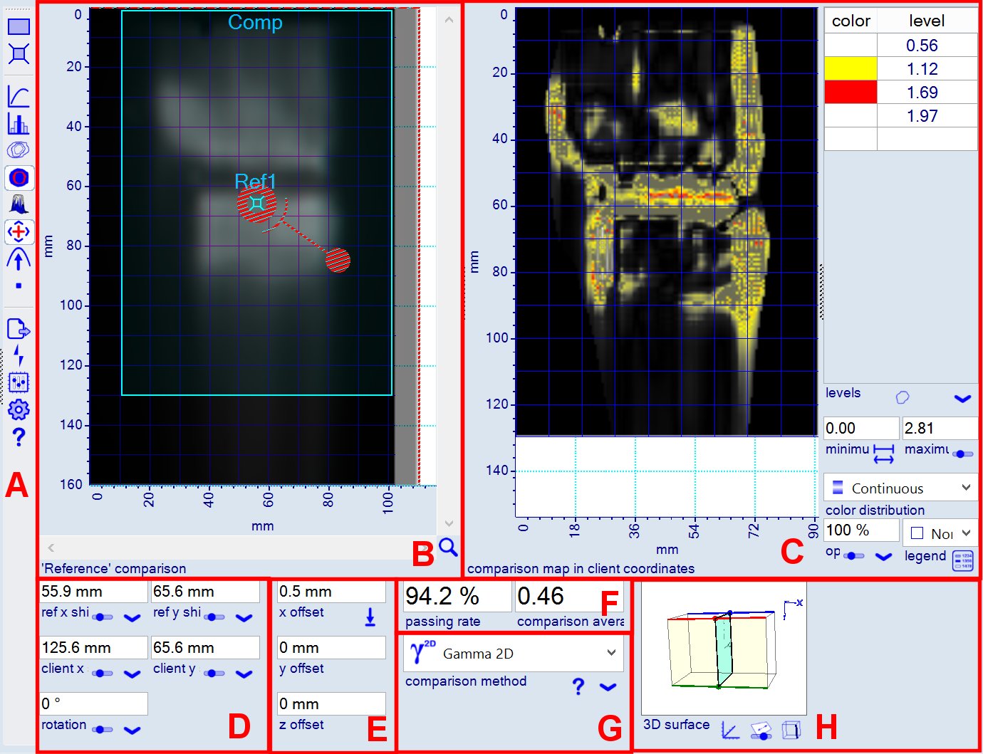
Section A - Tool Selector Bar
| Frame Selector | Select comparison area - none for overlap area of reference image and registered client image. See also editor Frame Selector tool. | |
| Fiducials, Markers | Select offset reference fiducials to measure offset between images in 2D or 3D. See also editor fiducials and markers for image registration. | |
| Profiles | Draw value profiles of the comparison map along a path line. See also editor Profile tool. | |
| Histograms | Chart histogram of the comparison map. See also editor Histogram tool. | |
| Contours | Draw contour lines along iso-value levels of the comparison map. See also editor Contour tool. | |
| Isomaps | Mark value ranges of the comparison map with dedicated color or value dependent gradients. See also editor Isomap tool. | |
| 3D surface | Draw 3D image surfaces of the comparison map. See also editor 3D surface tool. | |
| Image registration Rotation pole |
Allows image registration by matching fiducials. Assign rotation pole to particular Referenc and Client image locations. Define default rotation pole location. |
|
| Optimize comparison | Modify positioning of the client image to improve comparison results (passing rate or comparison value statistics).
2D: Client image (plan) is shifted and rotated to optimize comparison. 3D: Like 2D, addionally, the surface position of the client image inside the 3D bitcube data is also modified. |
|
| Pause tools |
Pause image tools, unselects current tool and renders tool utilities into non-edit mode. depending on tool 'Auto hide' option any tool specifiC panels or utilities are hidden when pause is selected. |
|
| Export tool | Exports comparison data in various formats to clipboard. | |
| Flip tool | Flips client image (plan) in case of 2D data. To flip client image when extracted from 3D bitcube, use surface properties. | |
| Chart settings | Modify chart scalling, image position, axis units, grid lines, fonts, lines, colors. | |
| Comparison tool configuration |
Manage image editor configuration (parameters). Loads, saves editor configuration to and from file. Copies, pastes editor configuration between different instances of OrthoChrome software. |
|
| Help | Link to web based help (e.g. this page). | |
| Hide tool bar | Hide tool bar to increase chart area. Only visible when cursor hovers over chart area. Use |
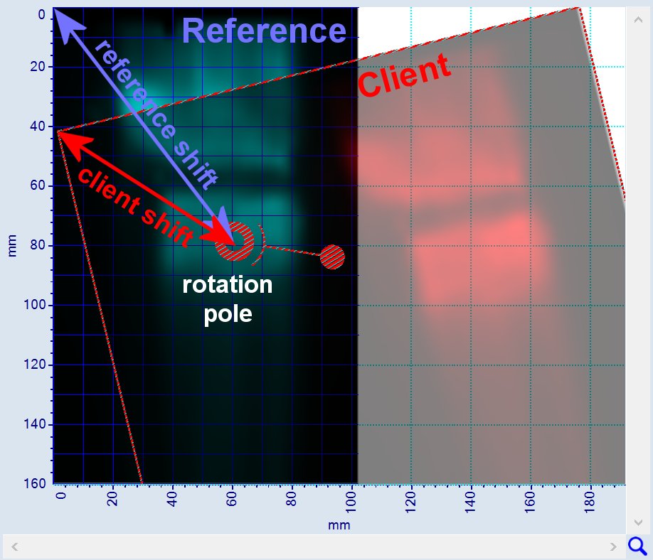
Section B - Image Overlay Chart
Chart shows overlay of Reference image (e.g. measured dose map) at background and Client image (e.g. plan) which can be shifted and rotated with respect to the reference image with top left corner anchored at coordinate origin.
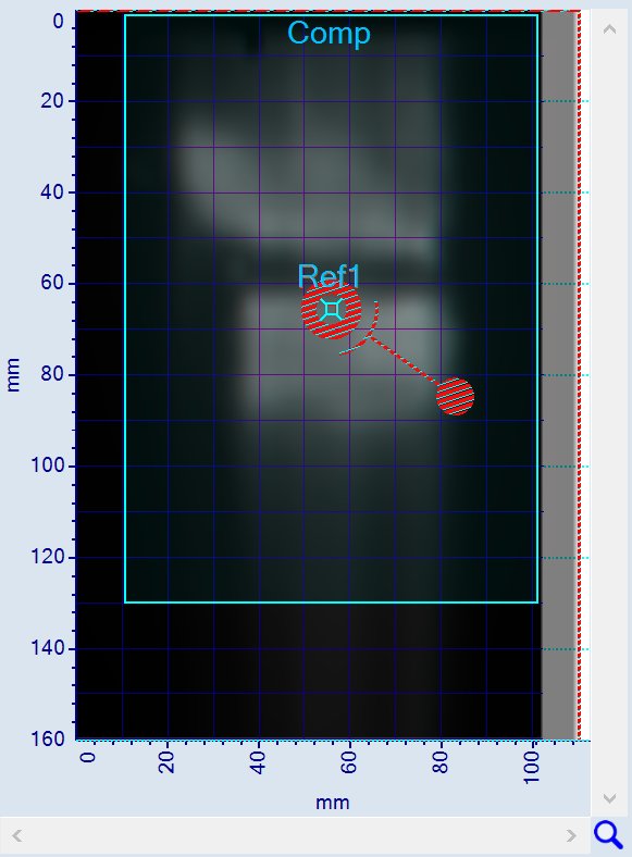
Reference image (default color Cyan) and Client image (default color red) are colored with complememtary colors, i.e. areas with matching values are gray. Areas where the reference values are greater than the client values apear in color of the reference image, and areas with values below the client values have the color of the client image.
Section C - Tool Chart
This area is reserved to display the data of the selected tool - the example below shows the comparison map as isomap.
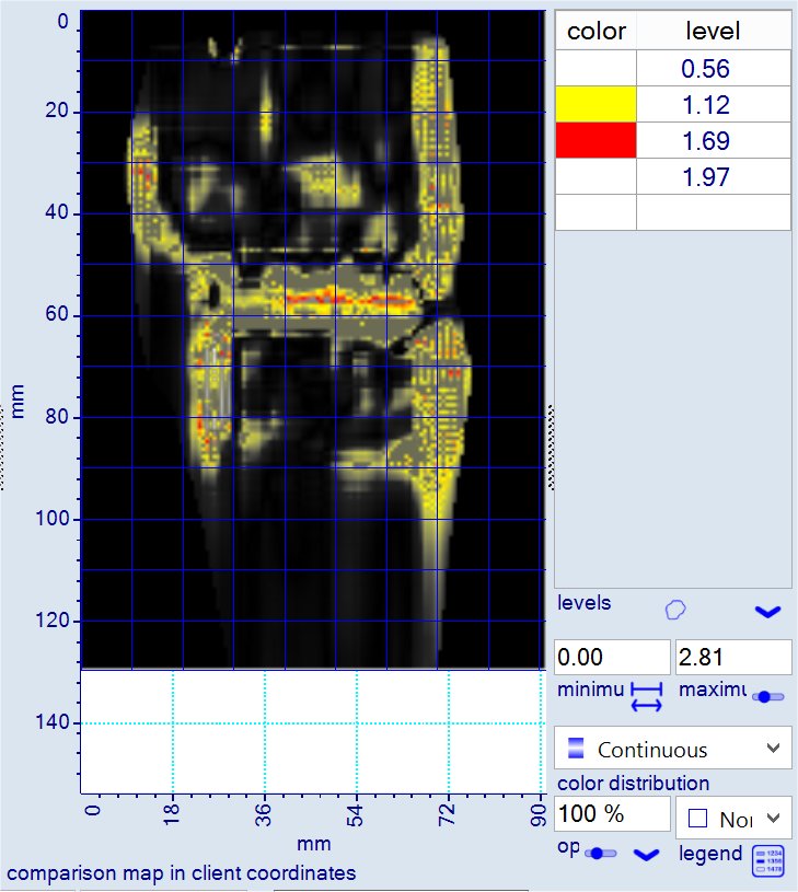
Some tools do Not have an own chart, in such cases the shown chart is that of the previously used tool. It will be displayed and updated until a tool is selected the claims this area.
Section D - Image Registration
The client image (plan) registration with respect to the reference image (measured dose map)
is defined by the distances of the rotation pole to the top left corners of the reference and the client image and the rotation angle.
The registration consits of:
- client shift (shifts the rotation pole of the client image to the coordinate origin)
- rotation angle (rotates shifted client image around origin)
- reference shift (shifts rotation pole to reference image location)
Those registration parameter are shown in the figure below.
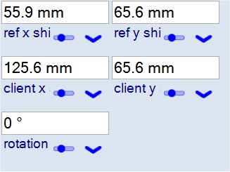
One of the coordinate shifts can be held constant (i.e. rotation pole location is kept constant either with respect to reference or to client image),
the registration is described by 3 parameters only.
2D optimization varies client shift and rotation angle to improve the comparison data (e.g. passing rate or comparison value).
3D optimization requires an additional shift along an anchor line inside the 3D bitcube. Optimization uses an anchor line that passes through
the center point of the bitcube.
In case the plan image describes a plane, the anchor line to optimize the 3D plan position is the normal direction through the center of the bitcube.
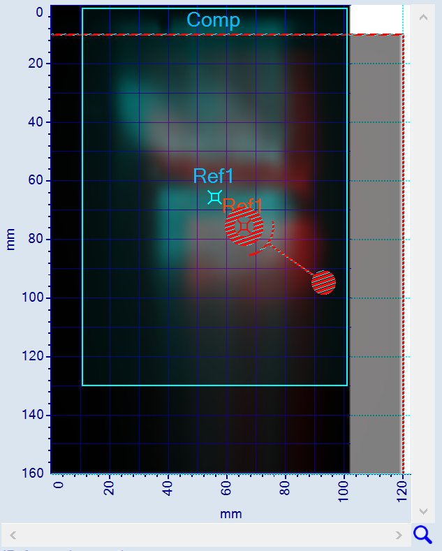
Section E - Offset
The 'offset' determines the position accuracy of a delivered dose field. This can be done by defining a number of 'offset reference' fiducials
at matching locations at the reference (dose map) and client image (plan) for a registration (e.g. initial registration defined by isocenter locations
at plan and dose map. After finding the 'best' registration that optimizes the comparison data (like passing rate), the offset at the stipulated
fiducial positions is a measure for the position accuracy.
This offset can be determined as 2D distance (i.e. distance at measurement plane that is assumed to be the same as plan plane) or as 3D distance
if the plan plane position inside the 3D bitcube is varied.
In general the plan plane can be any contineous surface through the 3D data (e.g. cylinder).
Both 3D and 2D offset can be measured with the OC software as long as 3D bitcube of plan data are provided.
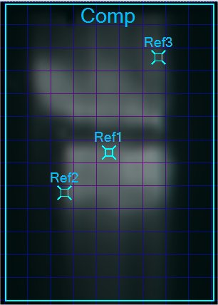
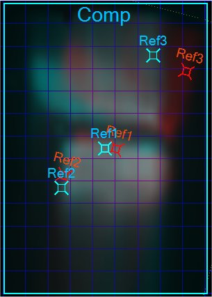
The figure above shows sets of 3 offset reference fiducials for different registrations.
If multiple fiducials are used, the offset value is the average of the single offset values.
In case of 3D offset measurement, the 3D offset reference points are defined by there 2D location at the plan surface (plane)
and the plane surface position in the bitcube.
Notes:
- When the plan surface position in the bitcube is unchanged, only the absolute length of the offset in 2D and 3D becomes the same.
- When the plan surface position in the bitcube changes, the image dimensions of the plan image might change. The fidcial location
at the new plan image is stipulate by the constant distance from the intersection point of the used anchor line with the plan surface (plane).
- There is no simple relationship between the components of corresponding 2D and 3D offset data,
e.g. the 2D offset could be zero whereas the 3D offset is substancially different from zero.
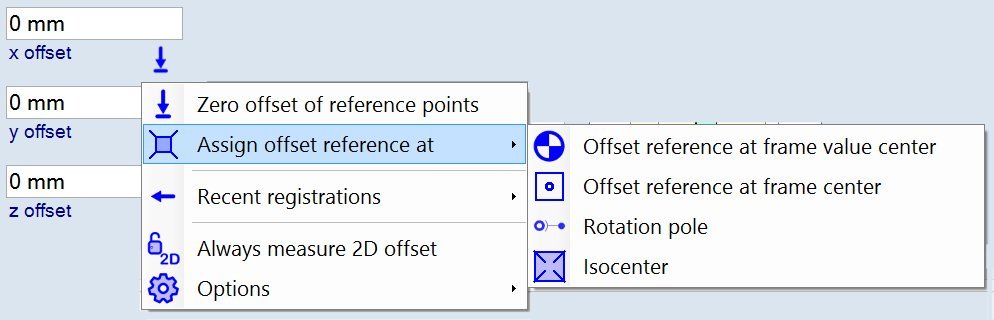
Offset parameters
| Zero offset of reference points | Projects offset reference points at reference image (dose map) to client image using current registration, i.e. offset becomes zero. | |
| Offset reference at | Assigns single offset reference fiducial to special location. | |
| Frame value center | Assigns offset reference at dose emphasis value across comparison region. | |
| Rotation pole | Assigns offset reference at current rotation pole location. | |
| Isocenter | Assigns offset reference at isocenter (perpendicular isocenter projection point). | |
| Recent registration | Select registration data from list of recently used registrations.
Note: When using optimization tool, registration before and after optimization are automatically saved. |
|
| Always measure 2D offset | When selected, 2D offset is always calculated. Otherwise, 3D offset is used when 3D data are available. | |
| Options | Further options. | |
| Zero offset before optimization | When selected, offset is set to zero before optimization is started. | |
| Default offset reference | Default offset reference location that is used when offset reference pounts are not present and new data are assigned or optimization is started.. |
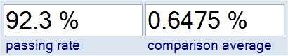
Section F - Comparison Result
Section G - Comparison Method
Selector for the method used to calculate the comparison map.
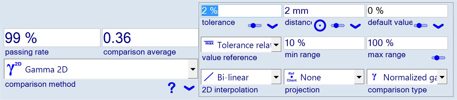
The
![]() button underneath the selector displays the parameters of the comparison method
as shown in the figure above.
button underneath the selector displays the parameters of the comparison method
as shown in the figure above.
Section H - 3D Plan Data
Compact panel to extract bitcube surface image (plan).
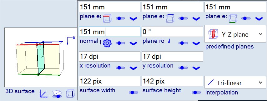
Bitcube surface parameters
| 3D view of the surface | Displays parameter panel to edit view of the 3D surface inside the cuboid. | |
| Surface 3D positioning | Displays the parameter to positioning the 3D surface insde the bitcube. | |
 |
3D surface parameter | Displays the parameters to extract the surface as shown in the figure above. |