


Parameter Settings
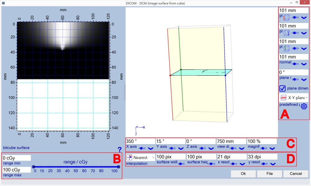
Section A - Plane definition
| Plane origin |
Defines plane location for origin (top left) of extracted image at 0° rotation. Red (default) edge in the cube display shows selected location. |
| Plane x axis |
Defines plane x axis location, x axis points from origin to that location. Defines the x axis at 0° rotation. Blue (default) edge in the cube display shows selected location. |
| Plane y axis |
Defines plane y axis location, y axis points from origin to that location. Defines the y axis at 0° rotation. Green (default) edge in the cube display shows selected location. |
 |
Intersection point edge selector. Note: Some edge combinations do Not allow to modify and map the plane properly. Restart with one of the predefined standard planes. |
| Normal position | Allows to relocate plane along the plane normal direction (parallel shift). |
| Plane rotation | Allows to relocate plane along the plane normal direction (parallel shift). At 0° the surface plane origin (upper left corner) is located at the cube edge marked as 'plane origin'. |
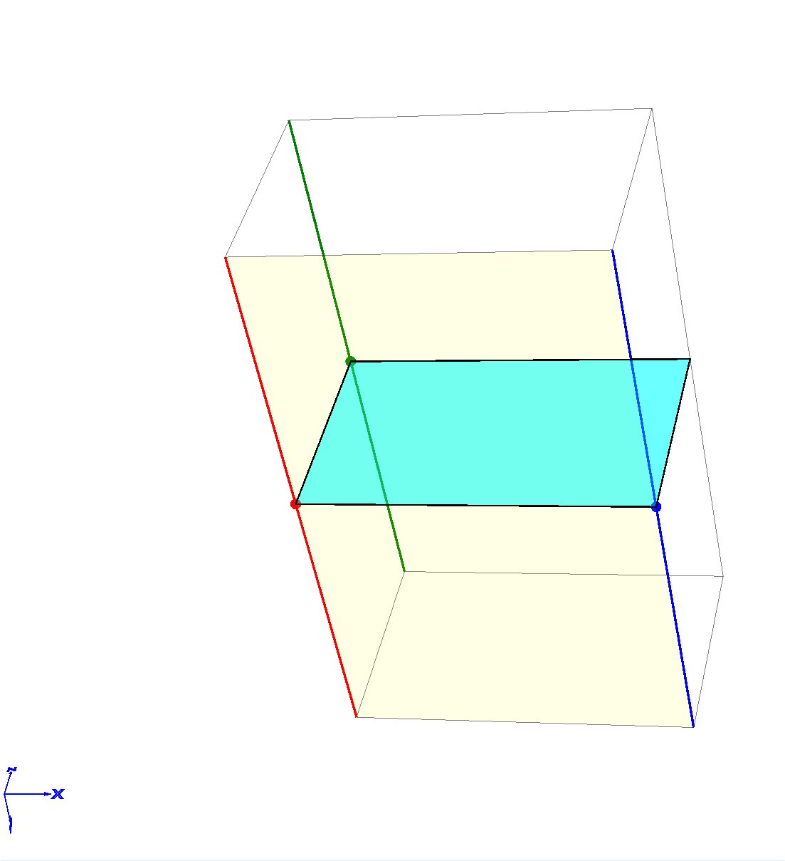
| Plane dimensions |
Indicates whether only the intersection area of the plane with the 3D cube is marked (example below right) Or
the plane area of the resulting image is drawn (example left). In the later case (option enabled), the origin (left upper corner)
of the resulting image is marked as well as direction of the x and y axes.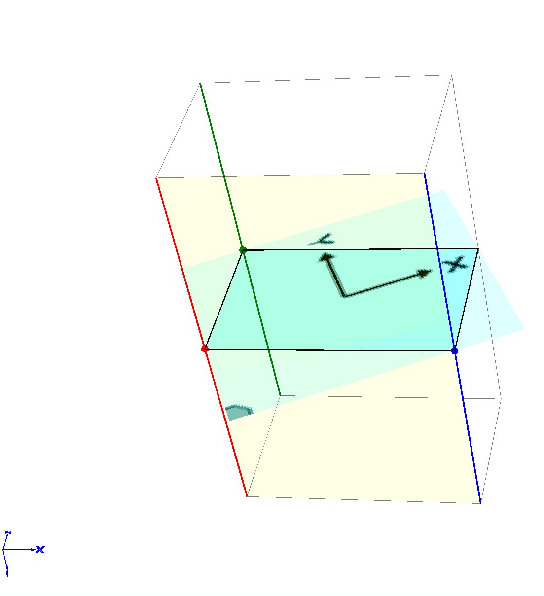
|
| Predefined planes | Selection of predefined standard planes including axial, coronal and sagittal planes as well as the cube faces. |
Section B - Image dose range
| Range min, max |
Dose range selection of extracted surface image. Some systems place marker pixels inside the 3D cube data that ditort the resulting images and render them complete white or black. Dose range selection truncates available dose range to compensate for those markers. |
Section C - 3D cube viewing
All parameters only change how the 3D cube is shown, they do Not change any properties of the surface plane.
| x, y, z axis rotation | Rotation of the 3D view around x, y and z axis. |
| View distance | View point (screen) distance from 3D cube center. The closer the view distance the stroner the perspective effect. |
| Magnification | Magnification factor of the 3D cube view with respect to default view (100%). |
Section D - Image approximation
| Interpolation |
Method to interpolate dose value at at surface plane from 3D cube data. Nearest - Nearest data point avilable in the 3D cube, fastest method, Tri-linear - linear interpolation in x, y and z direction, Tri-cubic - cubic interpolation in x, y and z direction, very slow (use only for final calculation) |
| Surface width, height |
Image size of the the extrapolated surface plane. Note: When the plane is rotated, its absolute size (size in m) changes, i.e. the resolution changes. Right click the label of the input field to select whether resolution is kept constant when rotating or modifying the plane in general. |
| X, y resolution. |
Image resolution of the the extrapolated surface plane in x and y direction. Note: Right click the label of the input field to select whether resolution in x and y direction is enforced to be the same. |